Simplified ATLAS calorimeter geometry
A (very) simplified version of ATLAS detector calorimeter incorporating the concept of a sampling calorimeter.
Instalation and execution
export Geant4_DIR=PATH_TO_GEANT4_INSTALL
#if using CERN-VMFS (https://ep-dep-sft.web.cern.ch/project/cernvm-fs)
#source setupCVMFS.sh
mkdir build; cd build
cmake ../ATLAS-simplified && make -j
Outline:
- Description - Description of the detector’s geometry (ECAL and HCAL)
- Resolution - Section about the detector responce and resolution
- Output - output files
- Scripts - List of scripts that conver the output files to different formats
1 Geometry description:
Full technical details on the electro-magnetic calorimeter (ECAL) design can be found in ECAL ref and on hadronic calorimeter (HCAL) design can be found in HCAL ref.
The detector granularity matches ATLAS geometry at η=0 (barrel). The detector composited from 6 layers: 3 form the Electro-Magnetic Calorimeter and 3 forms the Hadronid Calorimeter. A side view of the detector setup is shown in Fig. 1.1.

1.1 ECAL geometry:
Electro-Magnetic calorimeter composed of 3 layers. It consists of passive layers, 1.5 mm each of lead (Pb) and a 4.5 mm gap of liquid argon (LAr) used as a sensitive layer. The passive lead layers are placed in accordion geometry shape, and the gaps were filled with LAr, as shown in Fig 1.2.
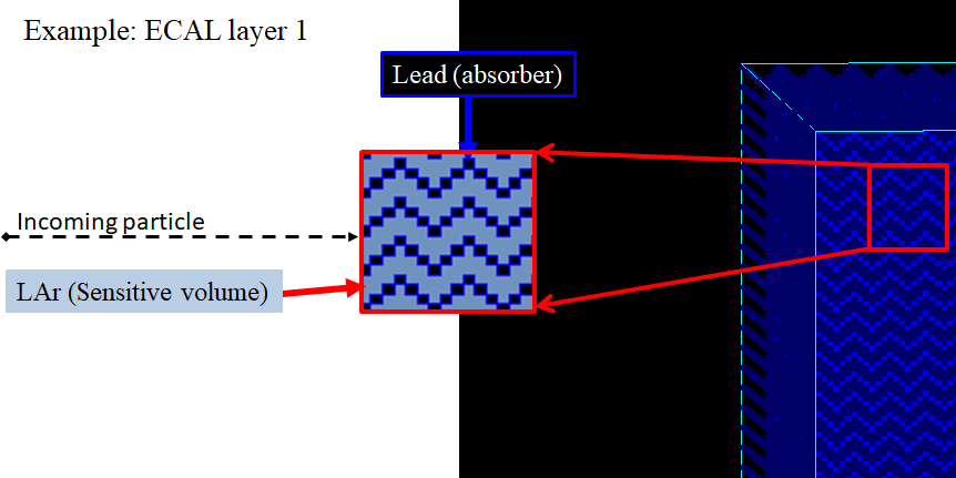
The energy resolution of ECAL geometry was simulated to be σ/E=6.9%/√E, which is controlled by electro-magnetic energy sampling fraction of about 25%.
Cell granularity was defined similar to ATLAS ECAL granularity at η=0:
| Layer | dx X dy [mm2] | dη X dφ | total X0 |
|---|---|---|---|
| ECAL 1 | 4.5 X 144 | 0.025/8 X 0.1 | 6 |
| ECAL 2 | 36 X 36 | 0.025 X 0.025 | 16 |
| ECAL 3 | 144 X 144 | 0.1 X 0.1 | 3 |
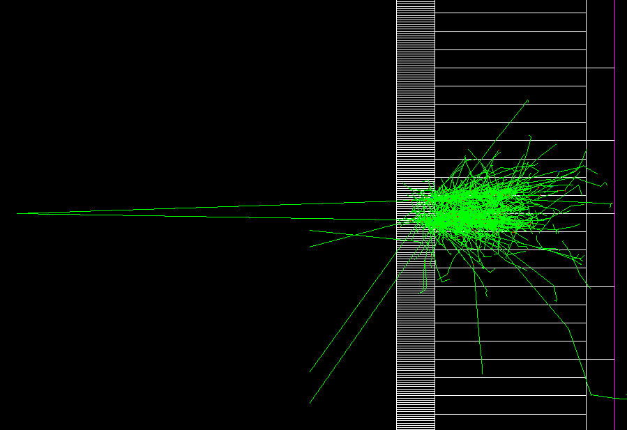
Exapmle of di-photon from 2 GeV π0 decay infront of the EM calorimeter is shown in Fig 1.3.
1.2 HCAL geometry
Hadronic calorimeter composed of 3 layers. It consists of passive layers, 5 mm each of stainless steel (Fe) and a 1 mm gap of the plastic scintillator (4-Vinyltoluene) used as a sensitive layer. Inside the passive region in parallel to the beam axis, the plastic scintillators are places, as shown in Fig 1.4.
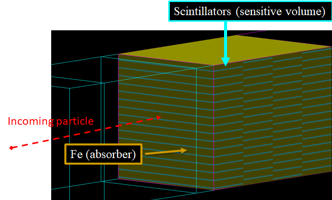
The energy resolution of HCAL geometry was simulated to be σ/E=40%/√E, which is controlled by electro-magnetic energy sampling fraction of about 2%.
Cell granularity was defined similar to ATLAS HCAL granularity at η=0:
| Layer | dx X dy [mm2] | dη X dφ | total λint |
|---|---|---|---|
| HCAL 1 | 144 X 144 | 0.1 X 0.1 | 1.5 |
| HCAL 2 | 144 X 144 | 0.1 X 0.1 | 4.1 |
| HCAL 3 | 288 X 288 | 0.2 X 0.2 | 1.8 |
2 Energy response
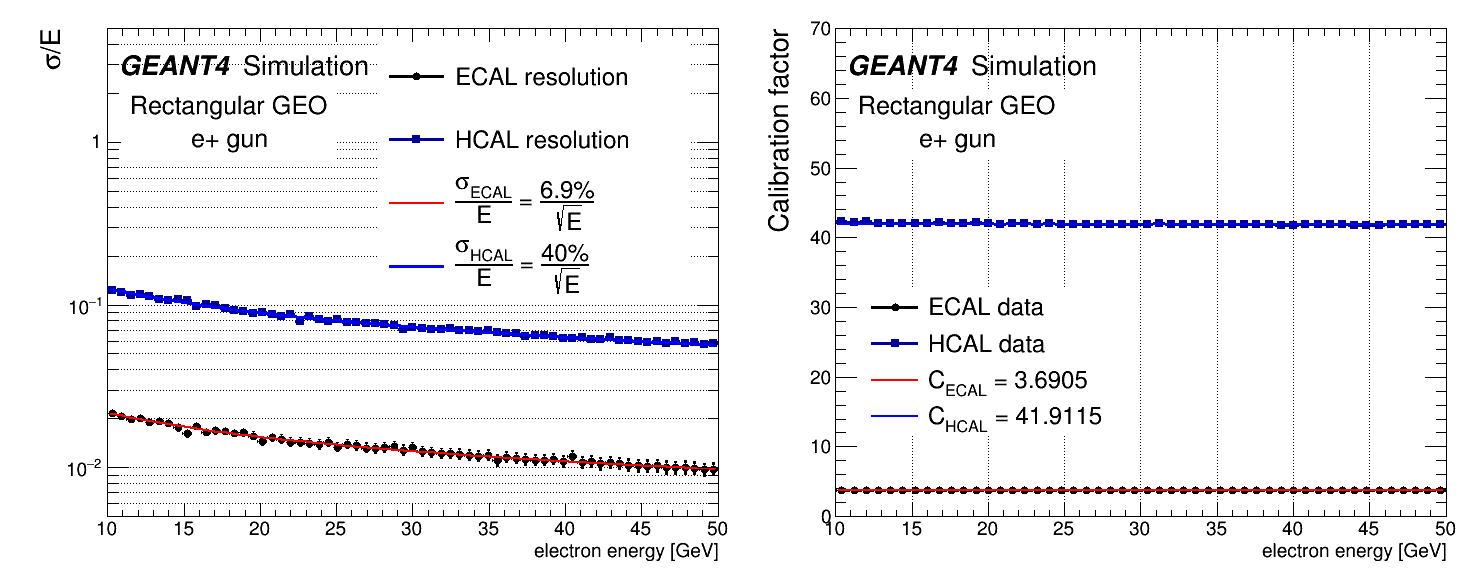
ECAL and HCAL were calibrated at EM scale, and a constant calibration factor of CECAL=3.6905 and CHCAL=41.9115 were extracted respectively, by shooting electrons in an energy range between 10 to 50 GeV.
Energy resolution and calibration factors are depicted in Fig 2.1
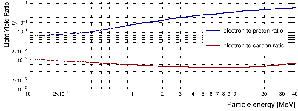
Besides the HCAL scintillator response function for hadrons was applied. Scintillator Light Yield depends on a particle type.
Using data for commercial scintillator (BC400)
energy deposits from hadrons were multiplied by Light Yield Ratio (LYR) factor obtained from the datasheet.
The LYR factor is shown in Fig 2.2.
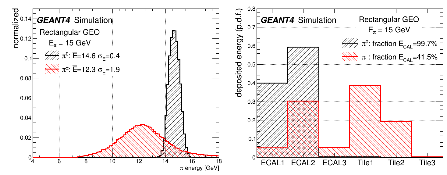
The detector energy resolution for 15 GeV pions is shown in Fig 2.3.
Output
The output is a ROOT file that contains vector<float> of cell energy and coordinates, as well as the information about primary particles.
In src/RunAction.cc implemenation of saving vectors in ROOT file using CreateNtupleDColumn of GEANT4 G4AnalysisManager instance is shown.
Scripts
To convert the output file that contains vectors of cells to 2D array execute:
root -l -q -b 'Vector2Matrix.cc("PATH_TO_FILE")'
To change resolutoin (degrade from high resolution image to low resolution image) use:
root -l -q -b 'Matrix2Matrix6L.cc("PATH_TO_FILE")'
the default setting are the ALTAS detector granularity
To convert the image with constant high granularity (all layers are of the same size), one can call the next function:
root -l -q -b 'Matrix6L2Matrix.cc("PATH_TO_FILE")'